Escalators Basic Components
Landing Platforms.
Truss.
Tracks.
Steps.
Handrail.
Escalator Exterior (Balustrade).
Drive system.
Auto-Lubrication System.
Braking system.
Safety devices.
Electrical & Control Systems.
And I explained the first six items in this previous topic. Today, I will explain other Escalators Basic Components as follows.
Seventh: Drive Systems

Drive Systems
An escalator drive system includes the following components:
Drive Machine and Gear Reducer.
The Step Drive System.
The Handrail Drive System.
The variation on how these two systems are combined is dependent upon the type of escalator. The Drive Machine used to drive the pinion gear or the main drive chain may directly or indirectly drive the Handrail Drive System.
1- Drive Machine and Gear Reducer

Drive Machine and Gear Reducer
A- Drive Machine
The Drive machine together with the gear reducer provides the torque to drive the step band at a constant speed.
The drive machine motor is typically a three-phase AC direct-on-line flange mounted unit. It is either directly or flexibly coupled to the reduction gear. The motor is usually protected by thermal and/or electro-magnetic overload devices as well as thermistors in the motor winding.
A.1 Types of Drive Machines:
There are three types of drive machines:
External Drive.
Internal Drive.
Modular Drive.
A.1.1 External Drive

External Drive
Machine is remotely located outside the truss in a different room/space or in the upper pit area. The Drive machine is located outside the truss.
The main drive machine is located in the upper pit area or in a separate machine room located below the upper section of the escalator. An external drive located in the upper pit area may employ a direct motor to gearbox drive, or a motor to gear reducer with a chain drive. An external drive escalator with the drive unit located within a machine room beneath the upper landing will normally employ a motor/gearbox with a chain drive extending to the upper landing.
A.1.2 Internal Drive

Internal Drive
Machine may be located at the upper landing inside the truss between the step bands or at the top pit, and will employ a motor to gearbox drive with a direct drive axle connection. A separate dual drive machine within the step band is not uncommon with one machine used to directly drive the step chains located a few feet below the upper incline and one above the lower incline. Internal escalator drive machines may be one, two, or three drive. A dual or three-machine may power the same main drive shaft or pinion shaft at the upper incline. Some internal drive escalators are equipped with either dual or three drive machines all inside the step band or step-belt.
A.1.3 Modular Drive

Machine is located within the incline of the truss between the step bands. The main drive is located within the incline of the truss within the step band. The motor may be directly connected to the gearbox or it may transfer power through a belt drive. The gearbox will have a direct connection to the drive axle. A modular escalator may have a single drive or a multiple drive depending on the overall length of the escalator.
A.2 Drive Machine Starting Methods
There are two common methods for drive machine starting as follows:
A.2.1 Conventional electromechanical starting systems, which include the following methods:
Full voltage Wye Start/Delta Run connection starting.
Part-winding starting.
Reduced voltage starting.
Auto-transformer starting.
Disadvantages of conventional electromechanical starting systems are as follows:
It requires a higher starting and running amperage.
It causes some wear and tear on the equipment with startups. The sudden jerk of the startup sequence was a shock to all the moving parts.
A.2.2 Solid-state soft-start controllers,

Solid-state soft-start controllers
The soft start controller is a solid state AC drive which controls the speed of AC motors by controlling the frequency and voltage of the power supplied to the motor.
It has the following advantages:
It can adjust the motor power to the number of riders using the escalator while maintaining normal speed.
It can reduce electricity use by a significant amount.
It allows for gradual smooth starting of three-phase squirrel cage motors.
It allow precise adjustment of motor starting torque, eliminating mechanical shocks which led to premature bearing wear, shaft and belt breakage, increased maintenance time, and costly production stoppages.
B- The Main Drive Gear (Gear Reducer)

The Main Drive Gear (Gear Reducer)
The Main Drive Gear or gear reducer assembly may be a single-stage type gear reducer. This is an enclosed, mechanical device that takes the drive motor torque and transmits this torque to the bull gear through a gearbox shaft (pinion) or the main drive chain. The gear reducer assembly contains a steel worm gear that is coupled or directly sleeved onto the motor shaft and it meshes with the pinion (bronze) gear.
2- The Step Drive System

Step Drive System
The step motion is achieved by a direct step assembly connection to the step chains.
Two-step chains; one for each side of the escalator are directly coupled to the Main Drive axle, the bull gear shaft, through the step chain sprockets. The step chain form a loop for the length of the truss, from the step chain sprockets at the upper end down to the tension carriage gear or turnaround (depending on the manufacturer) at the lower end or the lower reversing station.

Step Drive System
The Main Drive Axle is driven by the motor and reducer assembly. Sprockets or bull gears (depending on the manufacturer). On both ends of the Main Drive Axle transfer power the Step Drive System. These sprockets or bull gears drive two step chains, one each for the right and left sides of the escalator, which are connected at the lower end of the escalator to the step chain sprockets of the Tension Carriage.
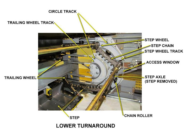
The Step Chains are endless links connected with link pins to make a complete loop and are attached to an axle on each side of the steps forming a loop which runs for the length of the truss from the upper Main Drive Axle to the lower Tension or Turnaround.
Circle Tracks (Crab Tracks)

Circle Tracks (Crab Tracks)
The Circle Tracks provide smooth step travel at the end of the tracks. The Chain Wheel is used to maintain proper tracking of the step chain. Most of the outer circle tracks have access windows for easy step removal.
3- Handrail Drive System

Handrail Drive System
The handrail drive moves the handrail along the handrail tracking system through traction on the V-shaped handrail underside. The handrail drives consists of the following:
The handrail drive and idler sheaves.
Handrail drive sprockets.
Handrail drive chains.
Handrail Take-Up Devices.
The Handrail Support Rollers.
A- The Handrail Drive and Idler Sheaves
They are V grooved sheaves located in the upper newel ends of the escalator. Idler sheaves are V grooved sheaves located in the lower newel ends of the escalator. The handrail drive sheave drives the handrail in its journey around the escalator while the idler sheave reverses the direction of the handrail at the lower end.
B- The Handrail Drive Chain Sprockets
They are located on the handrail drive sheave and the outboard end of the bull gear shaft. Handrail drive sprockets are linked by the handrail drive chain and provide a direct link between the bull gear and handrail drive sheave.
C- The Handrail Drive Chains
They are double stranded chains and are the mechanical link between the dual toothed drive chain sprockets. The drive chain sprockets and handrail drive chain coming to transfer power from the bull gear shaft to the handrail drive sheave. The Handrail drive chain has an adjustable take-up sprocket to keep the drive chain snug. The handrail drive chain receives lubrication from an enclosed bath system.
D- The Handrail Take-Up Devices
They are located directly downhill from the handrail drive sheaves. The handrail take-up devices remove slack in the handrail to provide the proper amount of slack in the handrail required to drive the handrail. The short handrail take-up device can be adjusted to remove slack from the handrail. The long handrail take-up device can pivot from the center and be adjusted at the uphill end to remove slack from the handrail. The long handrail take-up device is always required.
E- The Handrail Support Rollers
They are located at various intervals down the incline. Their function is as follows:
They support the handrail and protect it from coming into contact with the track brackets or any other truss components which may damage the handrail.
They help provide the correct loop of slack in the handrail at the lower end which proves the traction to drive the handrail.
Eighth: Auto-Lubrication System

Auto-Lubrication System
The escalators have an Automatic Lubrication System that supplies oil to lubricate the main drive chain, step chain, and the handrail drive chains. Oil flow rate is adjustable by setting the automatic timer control “off” and “on” periods to supply more or less lubrication.
The Automatic Lubricator has a gage to show oil reservoir level. The Lubrication Timer can be programmed for any time mode but, is pre-set for a 20 hour cycle. The system dispenses pre-determined amounts of oil to the distribution network which delivers this oil to the bearing points.
Note: The Auto Lubrication System does not supply grease to the drive system bearings. Drive bearing lubrication must be done manually. Bearings that need to be manually lubricated are the Main Drive Bearings, the Tension Carriage Bearings, the Motor Bearing, and the Handrail Drive bearings.
Additionally, the bearing surface of the Main Drive Shaft Brake, the Step Axle sleeve, the Step Wheel guide-shoe, and the Gear Box are manually lubricated.
Ninth: Braking Systems

Braking Systems
The braking systems on an escalator utilize three different braking methods as follows:
The Machine Brake.
The drive shaft brake system.
The Main Drive Shaft Brake.
1- The Machine Brake
It is an electromagnetically released, spring-applied, disk that is driven by a spline hub mounted to the extended worm input shaft of the gear-reducer. This type of brake is referred to as a fail-safe brake. When the brake coil is de-energized, springs within the assembly press the armature against the disc, and slowly stop the escalator. If an emergency button is pushed, if any of the safety switches are opened, or if there is a loss of power, the coil will be de-energized and the machine brake will be engaged.
2- The drive shaft brake system
It is also known as the Step Chain Locking Device or the broken drive chain device. It is often referred to by this name when it is used for maintenance purposes to lock the drive system. In this case, the guide shoe is removed to allow the pawl to drop and engage the ratchet.
3- The Main Drive Shaft Brake
It uses a pawl that is welded onto one end of the main drive shaft to engage a ratchet wheel with brake linings on both faces. The brake lining wheel is sandwiched between the handrail 1st drive sprocket and the step chain sprocket.
A guide shoe lever is welded onto the opposite end of the main drive shaft. The guide shoe is normally supported by the drive chain and when the chain breaks, the shoe drops and turns the shaft. The drive shaft brake pawl moves into the ratchet wheel and stops the escalator when the guide shoe drops.
Tenth: Safety devices

Safety devices
Escalator systems are provided with many safety devices that will automatically stop the escalator by cutting electrical power to the motor and applying the brake if a problem occurs. When a safety device stops the escalator, the problem must be corrected and the fault cleared before restarting the system.
If a safety device is tripped out, a corresponding safety relay (PLC Input/output) will drop out. This applies voltage to the latching circuit of that device. If any safety circuit control is tripped, the escalator will not operate and the tripped devices will do one of the following actions:
It will automatically reset when the fault is corrected.
It will require resetting only the main safety reset button inside the controller.
It will require that the individual controller circuit for that device must also be reset.
Safety Devices Types:
there are so many safety devices included in the escalators as follows:
1- The Broken Drive Chain Device, or Step Chain Locking Device/Pawl Brake, is a ratchet- type device that prevents the escalator steps from sliding down from the weight of passengers if the drive chain breaks.
2- A Broken Step Chain Device (tension carriage) cuts power to the motor and applies the brake if the step chain breaks or if the step chain is loose.

Broken Step Chain Device
3- A Skirt Obstruction Device cuts power to the motor and applies the brake if an object is wedged between the skirt panel and a step. This type of deflection will depress one of the plunger limit switches that are located behind the skirt panel at the upper and lower transitions and at intervals between.

Skirt Obstruction Device
4- A Comb Step Impact Device cuts power to the motor and applies the brake if a jam occurs between the comb plate and a step.

Comb Step Impact Device
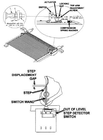
5- A Step Level Device cuts power to the motor and applies the brake if either side of the step at the riser end is depressed downward more than 1/8” or, if the step chain axle is depressed downward more than 1/8”.

Step Level Device
6- A Missing Step Device cuts power to the motor and applies the brake if an opening is detected in the step band.

Missing Step Device
7- The Broken Step Device is triggered if any of four roller lever limit switches are tripped. Two of the roller switches are located below the main drive and two are located below the tension carriage. When an out-of-place step trips the switch, power is cut to the motor and the brake coil will be de-energized.

Broken Step Device
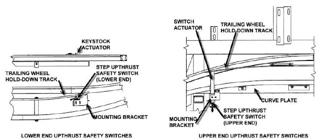
8- A Step Up-Thrust Device is located at the transition from the incline to the flat section of the truss.

Step Up-Thrust Device
9- Handrail Entry Device is located at the handrail entry port of each newel section. This device will cut power to the motor and apply the brake if an object is wedged between the handrail and the rubber entry guard. Any caught object will depress two switches behind the handrail guard.

Handrail Entry Device
10- A Broken Handrail Device is located in the escalator incline section. The device consists of a hinged roller that is held up by handrail tension. If a handrail is stretched or broken, a limit switch is depressed by the roller bracket dropping. When the switch is pressed, it cuts power to the motor and applies the brake. The safety reset button in the controller must be pressed to restart the escalator.

Broken Handrail Device
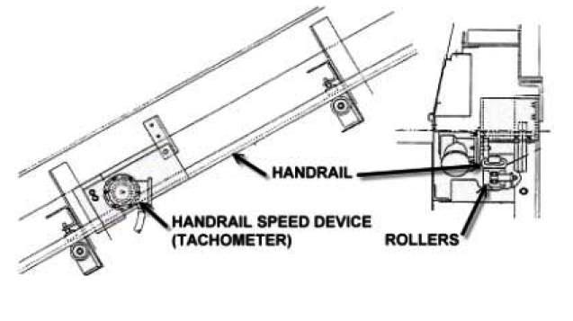
11- The Handrail Speed Device is a 1000 RPM tachometer generator wheel that rolls on the handrail. The weight of the tachometer generator and wheel pivots on a bracket to hold the wheel against the handrail. Contact of the tachometer wheel on the moving handrail turns the generator, which outputs a voltage of 6.72 volts. If the handrail speed drops below 80% or increases more that 110% over this voltage, then power to the escalator motor is cut and the brake is applied.

Handrail Speed Device
12- A Reversal Stop Device immediately stops the escalator when the direction of an ascending escalator is reversed. This device is located just above the incline section of the escalator. It consists of a lever clamped to the middle handrail shaft which rotates in the direction of travel. If the shaft direction is reversed, the lever will rotate and trip the switch, cutting power to the motor and brake.

Reversal Stop Device
13- An Emergency Stop Button is provided at both the upper and lower landing of the escalator. This covered button allows anyone to stop the escalator immediately in the event of an emergency. Lifting the cover of the emergency stop button will cause an alarm to sound for five minutes or until the escalator is restarted. Pressing the button will stop the escalator immediately. The escalator can be restarted after releasing the button by using the normal start-up procedure.

Emergency Stop Button
14- A Thermal Overload Relay is installed on the controller panel to protect the electrical drive motor from burning out due to escalator overload or a current overload. The relay can be reset by pressing the “Reset” button on the top of the Overload Relay.
15- MECHANICAL SAFETY DEVICES There are several mechanical safety devices that are used to stop and prevent movement of the escalator. These include locking bars, emergency brakes, and skirt brushes.

MECHANICAL SAFETY DEVICES
In the next Topic, I will continue explaining the Escalators Electrical & Control system and Moving Walkways. So, please keep following.
Note: these topics about Escalators in this course EE-1: Beginner's electrical design course is an introduction only for beginners to know general basic information about Escalators as a type of Power loads. But in other levels of our electrical design courses, we will show and explain in detail the Escalators Loads Estimation calculations.


 Skirt Obstruction Device

 Missing Step Device

 Handrail Entry Device


